fredag den 17. maj 2024

RS-232 probe

This RS-232 probe is useful when troubleshooting a serial connection. It provides an optical indication of the line state and traffic on the line. 

Figure 1. Circuit diagram.

RS-232 has two states: +3 to +15 volt (logic 0, space) or -3 to -15 volt (logic 1, mark). The RS-232 probe displays the two states using LEDs, and you can see the states changing. The maximum baud rate on the line is 9600 baud. At faster speeds, you cannot see the LEDs flashing. 

The bit length in a 9600 baud signal is 104 microseconds, and with 10 bits being sent, the flashing will last about 1 milliseconds. The flashing can be detected by the naked eye. 

Please refer to figure 1. If the input of the probe is higher than 2.7 volt, the red LED is on (green LED is off). If the input is lower than -2.7 volt, the green LED is on (red LED is off).

The RS-232 probe is powered by two 9 volt batteries. The current consumption is low, and the batteries can last for a long time. Don't forget to disconnect the batteries when the probe is not used. 

Figure 2. Veroboard.

All components are fitted on a piece of Veroboard. This is my preferred way of building electronic circuits! The dent on LED1 faces away from T1. The dent on LED2 faces T2.

Best 73 from OZ1BXM Lars
My homepage: oz1bxm.dk

onsdag den 15. maj 2024

TTL probe

This TTL probe is helpful when troubleshooting a serial connection. It provides an optical indication of the line state and traffic on the line. 

The TTL signal has two states: 0 volt or 5 volt. The TTL probe displays the two states using LEDs, and you can see the states changing. The maximum baud rate on the line should be 9600 baud (lower is better). 

The bit length in a 9600 baud signal is 104 microseconds, and with 10 bits being sent, the flashing will last about 1 milliseconds. The flashing can be detected by the naked eye. 

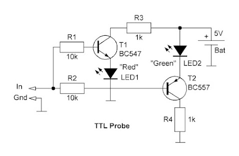
Figure 1. Circuit diagram.

If the input of the probe is between 0 V and 2 V, the green LED is on (red LED off). If the input is between 3 volt and 5 volt, the red LED is on (green LED off).

The TTL probe is powered by 5 volt DC. This voltage can be taken from the measured circuit, or from a external PSU. Even a 4.5 volt battery can be used.

Figure 2. Veroboard.

All 8 components are fitted on a piece of Veroboard. This is my preferred way of building electronic circuits! The dent on LED1 faces away from T1. The dent on LED2 faces T2.

The circuit was copied from DIY Logic Probe: Step by Step Guide.

Best 73 from OZ1BXM Lars
My homepage: oz1bxm.dk