|
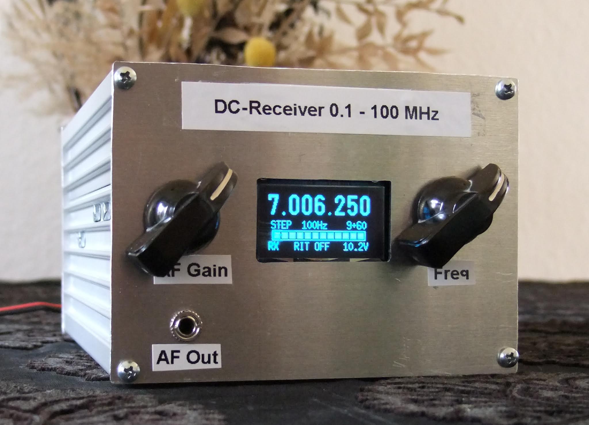
| Fig. 1. DC-receiver seen from the front. |
Building your own equipment is not difficult if you buy ready-made modules and connect them together. I wanted to to build a DC (Direct Conversion) receiver with a broad frequency range.
 |
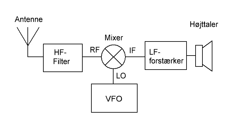
| Fig. 2. Direct Conversion concept. |
The concept of Direct Conversion is shown in figure 2. Four modules make up a SSB/CW receiver, and all modules can be obtained ready-made!
HF-filters are usually sold as kits or ready-made. I decided to make my own filter using a piece of Veroboard. The filter's circuit diagram and the Veroboard are shown below.
 |
| Fig. 3. The 7 MHz bandpass filter. |
 |
| Fig. 4. The filter is build with leaded components on a piece of Veroboard. |
The mixer is a ready-made board centered around AD831. AD831 is an active, double-balanced mixer from Analog Devices and it runs on 10 V DC at 100 mA. The required LO level is just -10 dBm and max. input on the RF-port is +10 dBm.
 |
| Fig. 5. Active mixer 0.1 - 500 MHz. |
The
AF-amplifier is the well-known LM386 having 46 dB amplification. I tried to find a modern substitute, but that was difficult. Many audio ICs amplify something like 26 dB, and that is too low for DC-receivers which require 40 dB amplification or more.
 |
| Fig. 6. AF-amplifier with LM386. |
The VFO is the ARDU-5351 kit sold by qrphamradiokits.com. The kit includes an OLED display, a rotary encoder, a frequency generator module (Si5351A), and the Arduino Nano. I soldered all parts onto the motherboard except the Nano, which is fitted using sockets. There was no soldering of SMD-components.
 |
| Fig. 7. The VFO kit. |
As the VFO output is 7 dBm, I've added a 20 dB attenuator to lower the output and comply with the LO port level of the active mixer.
Components for power distribution and the S-meter rectifier are fitted on a piece of Veroboard as shown in figure 8 below.
 |
| Fig. 8. The 10 V power supply and the S-meter rectifier. |
 |
| Fig. 9. Circuit diagram. |
All modules are fitted into a metal enclosure which I acquired from Conrad Electronics (item 522953). The enclosure's front is seen in figure 1 above, and the rear is seen in figure 10 below. Figure 11 shows the open enclosure.
 |
| Fig. 10. Rear side of the DC-receiver. |
 |
| Fig. 11. The DC-receiver with lid removed. |
Vy 73 from OZ1BXM Lars
Homepage: http://oz1bxm.dk/