![]() |
| Figure 1. Wiring of I2C. |
![]() |
| Figure 2. I2C scanner with Arduino UNO. |
![]() |
| Figure 3. Output from the I2C-scanner |
![]() |
| Figure 1. Wiring of I2C. |
![]() |
| Figure 2. I2C scanner with Arduino UNO. |
![]() |
| Figure 3. Output from the I2C-scanner |
![]() |
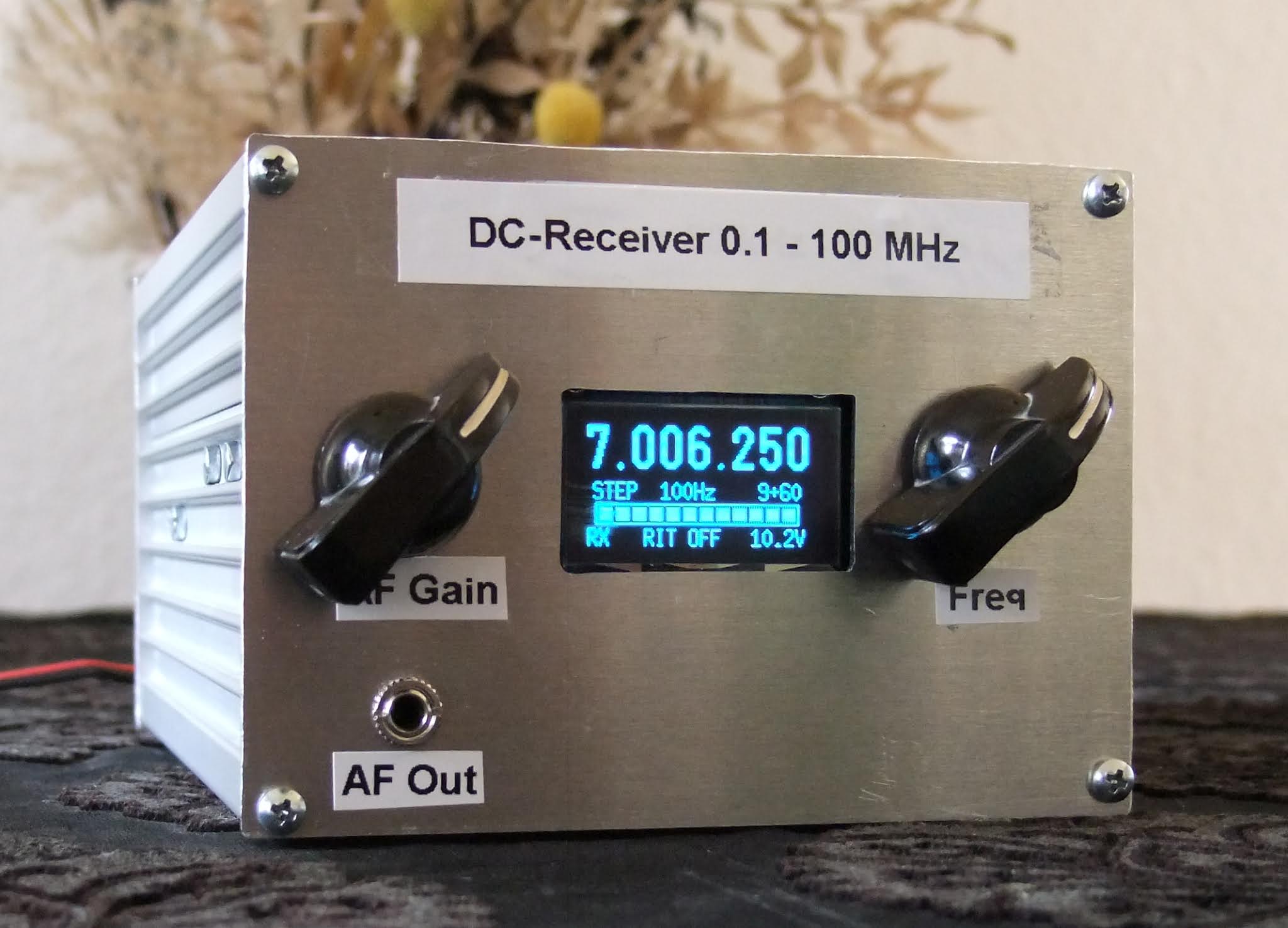
| Fig. 1. DC-receiver seen from the front. |
Building your own equipment is not difficult if you buy ready-made modules and connect them together. I wanted to to build a DC (Direct Conversion) receiver with a broad frequency range.
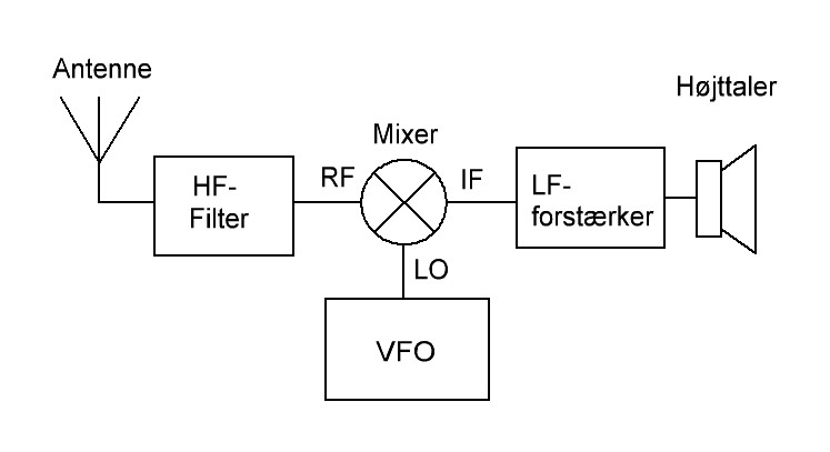
| Fig. 2. Direct Conversion concept. |
| Fig. 3. The 7 MHz bandpass filter. |
![]() |
| Fig. 4. The filter is build with leaded components on a piece of Veroboard. |
![]() |
| Fig. 5. Active mixer 0.1 - 500 MHz. |
![]() |
| Fig. 6. AF-amplifier with LM386. |
The VFO is the ARDU-5351 kit sold by qrphamradiokits.com. The kit includes an OLED display, a rotary encoder, a frequency generator module (Si5351A), and the Arduino Nano. I soldered all parts onto the motherboard except the Nano, which is fitted using sockets. There was no soldering of SMD-components.
![]() |
| Fig. 7. The VFO kit. |
As the VFO output is 7 dBm, I've added a 20 dB attenuator to lower the output and comply with the LO port level of the active mixer.
Components for power distribution and the S-meter rectifier are fitted on a piece of Veroboard as shown in figure 8 below.
![]() |
| Fig. 8. The 10 V power supply and the S-meter rectifier. |
| Fig. 9. Circuit diagram. |
All modules are fitted into a metal enclosure which I acquired from Conrad Electronics (item 522953). The enclosure's front is seen in figure 1 above, and the rear is seen in figure 10 below. Figure 11 shows the open enclosure.
![]() |
| Fig. 10. Rear side of the DC-receiver. |
![]() |
| Fig. 11. The DC-receiver with lid removed. |
Vy 73 from OZ1BXM Lars
Homepage: http://oz1bxm.dk/
I've used Network Time about 6 months. However, the PC clock deviation could be 500 ms or more during a day. This amount of drift is not acceptable - digital modes like JT65 and FT8 require less than 100 ms deviation in order to run smoothly.
A blog post by N1RWY directed me to BktTimeSync by IZ2BKT Capelli Mauro.
Main page and software download: BktTimeSync
Alternative page for download: https://bkttimesync.software.informer.com/
My configuration is shown in figure 1. Note that connecting to an NTP-server works only if the PC firewall allows traffic on port 123. "GPS Configuration" is not filled in as I don't use a GPS device as time source.
BktTimeSync should run automatically when the PC starts up. How to add an app to run automatically at startup in Windows 10 is described by Microsoft support.
Fig. 2. Message from time.is: You have the exact time!
Checking your PC clock can be done by visiting time.is. You'll discover if your PC clock is off. Figure 2 shows, that my PC clock has the exact time, and the deviation is just 6 ms.
I hope BktTimeSync will continue its excellent timekeeping on my PC!
Note december 2020: BktTimeSync is still running on my Win 10 PC. System time is updated every 20 min via europe.pool.nt.org. I am satisfied with it's performance.
73 OZ1BXM Lars
Homepage: oz1bxm.dk
![]() |
| My 23 cm portable rig at Trehoje JO46HE. |
![]() |
| Figur 1. The noisefree PSU. |
![]() |
| Figure 2. Noisefree PSU with open lid. |
![]() |
| Figure 3. AC Adaptor. |
| Figure 4. Circuit diagram. |
![]() |
| Figure 5. The circuit board seen from the bottom. |