fredag den 17. maj 2024

RS-232 probe

This RS-232 probe is useful when troubleshooting a serial connection. It provides an optical indication of the line state and traffic on the line. 

Figure 1. Circuit diagram.

RS-232 has two states: +3 to +15 volt (logic 0, space) or -3 to -15 volt (logic 1, mark). The RS-232 probe displays the two states using LEDs, and you can see the states changing. The maximum baud rate on the line is 9600 baud. At faster speeds, you cannot see the LEDs flashing. 

The bit length in a 9600 baud signal is 104 microseconds, and with 10 bits being sent, the flashing will last about 1 milliseconds. The flashing can be detected by the naked eye. 

Please refer to figure 1. If the input of the probe is higher than 2.7 volt, the red LED is on (green LED is off). If the input is lower than -2.7 volt, the green LED is on (red LED is off).

The RS-232 probe is powered by two 9 volt batteries. The current consumption is low, and the batteries can last for a long time. Don't forget to disconnect the batteries when the probe is not used. 

Figure 2. Veroboard.

All components are fitted on a piece of Veroboard. This is my preferred way of building electronic circuits! The dent on LED1 faces away from T1. The dent on LED2 faces T2.

Best 73 from OZ1BXM Lars
My homepage: oz1bxm.dk

onsdag den 15. maj 2024

TTL probe

This TTL probe is helpful when troubleshooting a serial connection. It provides an optical indication of the line state and traffic on the line. 

The TTL signal has two states: 0 volt or 5 volt. The TTL probe displays the two states using LEDs, and you can see the states changing. The maximum baud rate on the line should be 9600 baud (lower is better). 

The bit length in a 9600 baud signal is 104 microseconds, and with 10 bits being sent, the flashing will last about 1 milliseconds. The flashing can be detected by the naked eye. 

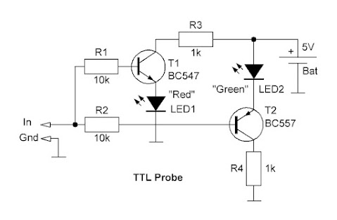
Figure 1. Circuit diagram.

If the input of the probe is between 0 V and 2 V, the green LED is on (red LED off). If the input is between 3 volt and 5 volt, the red LED is on (green LED off).

The TTL probe is powered by 5 volt DC. This voltage can be taken from the measured circuit, or from a external PSU. Even a 4.5 volt battery can be used.

Figure 2. Veroboard.

All 8 components are fitted on a piece of Veroboard. This is my preferred way of building electronic circuits! The dent on LED1 faces away from T1. The dent on LED2 faces T2.

The circuit was copied from DIY Logic Probe: Step by Step Guide.

Best 73 from OZ1BXM Lars
My homepage: oz1bxm.dk 

tirsdag den 9. april 2024

ADX-S - Arduino Transceiver for Digimode

ADX-S stands for Arduino Digital Transceiver - Superheterodyn. ADX-S is a QRP transceiver with four modes: WSPR, FT8, FT4 and JS8. There are two versions available; one with 4 bands (40m, 20m, 15m, 10m) and another one with 7 bands (40m, 30m, 20m, 17m, 15m, 12m, 10m). 

ADX-S is open source. I decided to build it from a 7-band kit sold by crkits.com. Help is available in the crkits group.

Figure 1. ADX-S front.

The ADX-S transceiver has 3 PCB with the same size: front plate, main board, rear plate. They all measure 9.7 cm x 9.7 cm. All components and connectors are on the main board. The front and rear plates are "sandwiched" to the main board using threaded distance bolts. This is a smart solution to the cabinet problem (cabinets for ham radio projects are difficult to source). 

Figure 2. ADX-S main board.

Assembly
Kit assembly went okay with one exception: I swapped L1 and L3 on some of the low-pass filter boards. This error made the output power disappear. After correcting the error, the low-pass filters worked just fine. The output is 2-3 watt RF depending on the chosen band.

The assembly challenge is medium. The solder pads are close and their size is small - this is not a beginner's task! An advantage of the kit is the lack of SMD-components. All components are leaded. Two units (Arduino Nano, SI5351) are populated with SMD, but they are assembled in a factory and are easily soldered to the main board using pins.

  Figure 3. ADX-S rear.

Frequency read-out
Figure 4. Reading the frequency band.

The frequency band can only be set (or read) during upstart of the ADX-S. During power-on the button "Band" is pushed. When the "TX" LED is lit, the band can be set using the two grey buttons. When finished, the "TX" button is pushed, and the band information is saved. Now the LEDs indicate mode. The band information is no longer visible.

During normal power-on, there will be 3 flashes from the LEDs to indicate the band. When flashing is done, the LEDs will show mode.

Receiver
The heart of the receiver is CD2003 which is a clone of Toshiba's integrated receiver TA2003. The receiver is superheterodyn with IF at 455 kHz and a ceramic filter for selectivity. The RF signal is taken from the low-pass filter. An RF switch isolates the receiver from the low-pass filter during transmit. The LO is generated by SI5351 (frequency generator for RX and TX).

Transmitter
The transmitter is surprisingly simple. The ordinary concept is to employ a DBM (double balanced mixer) and LO to get from AF to the transmit frequency. Instead, the transmit frequency is generated directly by the programmable SI5351. The output from SI5351 is amplified and sent to 3 transistors connected in paralled (3 x BS170 MOSFET). The LPF (low pass filter) is on a small PCB which is connected to the main bord with pins. The LPF is specific for each band, and is swapped when changing band. 

Connecting to a computer

Figure 5. Connecting ADX-S to a computer.

Figure 5 shows how the ADX-S is connected to a computer. Computer software is WSJT-X (free) and this software codes and decodes FT8, FT4, and WSPR. Different software is used for JT8.

An Android smartphone can replace the computer. In that case the app FT8CN is installed.

73 from OZ1BXM Lars 

My homepage: www.oz1bxm.dk

mandag den 14. august 2023

DIY 70 cm yagi 6 elements

Figure 1.

I needed a short 70 cm yagi for working the LEO satellites. In earlier years, I've had a 6-element yagi and I was satisfied with its performance. So I decided to build such an antenna.

Figure 2. 

The antenna measurements came from ON6MU. However, I made my own drawing (figure 2). All elements and the dipole were made according to the recommendations by ON6MU. Only the boom is a bit slimmer (15 x 15 mm instead of 20 x 20 mm). I had the tubes and the boom lying around, and assembly was easy. The measurements must be accurate down to the millimeter - and that was a challenge!


Figure 3.

The black element holders were found in the scrap-box. They were acquired some years ago from hfkits.com (link: Yagi element holder for 15x15 mm boom - HF kits). The balun is copied from innovantennas - they use the same concept. 4-5 tight loops of coax-cable prevents HF-currents running on the outside of the cable. I used 150 cm RG-400 teflon coax, and it was terminated with an N-connector. Figure 3 shows the balun before it was made water-proof.   

Figure 4.

Figure 4 shows how the dipole is mounted on the boom using 2 element holders. The dipole is isolated from the boom. The coax-cable center conductor is soldered to the left solder lug; and the coax braid to the right one.

I did not use stainless screws and mutters for assembly, so I painted all screws/mutters after fitting them to avoid corrosion. Where the coax-cable is connected to the dipole, the cable was secured against moisture. I used PlastiDip for this purpose. Otherwise, the braid may detoriate due to water ingress.

The antenna was mounted on a 1½" steel mast turned by a rotator (Yaesu G-600). From 7.5 meters above ground, the antenna heard two terrestical UHF beacons: OZ7IGY at 227 km (weak signal) and LA8UHF at 322 km (normal signal). I listened for the LEO satellite RS-44, and its beacon was heard at a distance of 4000 km. The antenna works to my satisfaction, and I'll use it from now on!

Antenna SWR is 1.3 between 432-438 MHz, and this figure is satisfactory.  

torsdag den 26. januar 2023

My first DXCC diploma

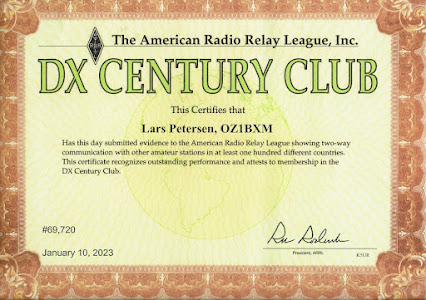
My first DXCC diploma arrived in the mail today. Shipping from USA to Denmark took 16 days. The mode is Mixed because CW and FT8 were used for my QSOs with 100 different entities (countries).


I have applied for DXCC before. It was around 1994. I sent QSL cards from 100 different countries to ARRL Headquarter in Connecticut. But my shipment newer arrived. It was called for in the postal system, but the envelope newer showed up - it was lost. Replacing 100 QSL cards is difficult, so I gave up DXCC for many years.  

I started with FT8 last year, and after some time, I discovered that DXCC was within reach. Another factor was Logbook of the World (LotW). This tool did not exist back in 1994, and LotW makes QSO confirmations fast, easy, and cheap. Many FT8 stations are using LotW for confirming their contacts. My DXCC diploma was confirmed by LotW for 94 entities, and QSL cards for 6 entities. The cards were checked by OZ1ACB who is the ARRL card checker in Denmark. 

Are there other diplomas in the pipeline? Yes, I am seeking QSOs for the QRP DXCC diploma, where all contacts must take place using a maximum of 5 W RF power on my side. Current status is 97 entities.   

73 from OZ1BXM Lars

Homepage: oz1bxm.dk

søndag den 8. januar 2023

First QSO via Greencube satellite

Greencube is an exciting satellite. The orbit is MEO (Medium Earth Orbit), and the average distance to Earth is 6,800 km. Greencube carries seeds for plants to grow under microgravity conditions.The results of this project will allow production of vegetables in space to support future human space missions. Future astronauts will have access to fresh and nutritious food along their journey!  

Greencube

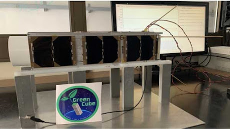
Greencube in the lab. Photo: Italian Space Agency.

Greencube is a tiny satellite measuring 10 cm x 10 cm x 30 cm. It was launched by ESA from French Guiana on 13. July 2022. NORAD ID is 53106. AMSAT has designated the satellite IO-117. The satellite carries a digipeater for ham radio operating at 435 MHz. 

IO-117 footprint

Greencube footprint (www.n2yo.com)

I've decided to operate via Greencube. The footprint is huge compared to the current LEO satellites. I have never tried operating a digipeater before. The distance to the satellite is between 6,800 km and 10,000 km. There are some challenges here!

Ground station

OZ1BXM ground station for Greencube.

My ground station for Greencube is a Yaesu FT-847 VHF/UHF transceiver. Greencube software runs on my Windows 10 computer. My antenna is a 9-element X-Quad (vertical polarization) controlled by 2 rotators, one for azimuth and one for elevation.

The challenge was installing the software. There were in total 6 different programs to install and configure. It took me several long days to complete.

I had my first QSO via IO-117 on January 6th with S57NML in Slovenia. It was fun and challenging. Later followed a QSO with W5CBF in Louisiana, USA. There is plenty of DX to chase on this satellite!

Link: ZR6TG Adventures with Greencube Satellite

Link: Tracking Greencube: https://www.n2yo.com/?s=53106

73 from OZ1BXM Lars, oz1bxm.dk

mandag den 5. december 2022

I've worked 100 entities using FT8

In July 2022, I challenged myself to pursuing 100 entities using FT8 and wire antennas. The pursuit is over now as I worked entity #100 on the 1st of December. The challenge lasted nearly 5 months.

The 100 entities are listed here: http://oz1bxm.dk/100-lande-ft8.html

My 100 entities distributed on continents.

The figure above shows the 100 worked entities distributed on continents. Most entities were from EU (Europe) and AS (Asia). Less frequent were AF (Africa) and NA (North America). SA (South America) and OC (Oceania) contributed with 8 entities. The reason for the EU majority: Living in Denmark makes it easy for me to contact European entities, and there are many of them!

My 100 entities distributed on frequency band.

The figure above shows the 100 worked entities distributed on frequency bands. I've worked most entities on the 20 meter and 15 meter bands. I've worked only 2 entities on the 80 meter band (the antenna was too short on 80 meters). The remaining bands contributed almost the same number of entities.

I've used low output power (20 W or less) for 99 of the entities. Only in one case 80 W was used. My antenna was a dipole (entity 1-70) and a horizontal wire loop 43 m long (entity 71-100).

Vy 73 from OZ1BXM