søndag den 8. januar 2023

First QSO via Greencube satellite

Greencube is an exciting satellite. The orbit is MEO (Medium Earth Orbit), and the average distance to Earth is 6,800 km. Greencube carries seeds for plants to grow under microgravity conditions.The results of this project will allow production of vegetables in space to support future human space missions. Future astronauts will have access to fresh and nutritious food along their journey!  

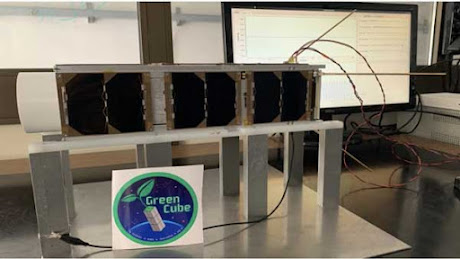
Greencube

Greencube in the lab. Photo: Italian Space Agency.

Greencube is a tiny satellite measuring 10 cm x 10 cm x 30 cm. It was launched by ESA from French Guiana on 13. July 2022. NORAD ID is 53106. AMSAT has designated the satellite IO-117. The satellite carries a digipeater for ham radio operating at 435 MHz. 

IO-117 footprint

Greencube footprint (www.n2yo.com)

I've decided to operate via Greencube. The footprint is huge compared to the current LEO satellites. I have never tried operating a digipeater before. The distance to the satellite is between 6,800 km and 10,000 km. There are some challenges here!

Ground station

OZ1BXM ground station for Greencube.

My ground station for Greencube is a Yaesu FT-847 VHF/UHF transceiver. Greencube software runs on my Windows 10 computer. My antenna is a 9-element X-Quad (vertical polarization) controlled by 2 rotators, one for azimuth and one for elevation.

The challenge was installing the software. There were in total 6 different programs to install and configure. It took me several long days to complete.

I had my first QSO via IO-117 on January 6th with S57NML in Slovenia. It was fun and challenging. Later followed a QSO with W5CBF in Louisiana, USA. There is plenty of DX to chase on this satellite!

Link: ZR6TG Adventures with Greencube Satellite

Link: Tracking Greencube: https://www.n2yo.com/?s=53106

73 from OZ1BXM Lars, oz1bxm.dk
mandag den 5. december 2022

I've worked 100 entities using FT8

In July 2022, I challenged myself to pursuing 100 entities using FT8 and wire antennas. The pursuit is over now as I worked entity #100 on the 1st of December. The challenge lasted nearly 5 months.

The 100 entities are listed here: http://oz1bxm.dk/100-lande-ft8.html

My 100 entities distributed on continents.

The figure above shows the 100 worked entities distributed on continents. Most entities were from EU (Europe) and AS (Asia). Less frequent were AF (Africa) and NA (North America). SA (South America) and OC (Oceania) contributed with 8 entities. The reason for the EU majority: Living in Denmark makes it easy for me to contact European entities, and there are many of them!

My 100 entities distributed on frequency band.

The figure above shows the 100 worked entities distributed on frequency bands. I've worked most entities on the 20 meter and 15 meter bands. I've worked only 2 entities on the 80 meter band (the antenna was too short on 80 meters). The remaining bands contributed almost the same number of entities.

I've used low output power (20 W or less) for 99 of the entities. Only in one case 80 W was used. My antenna was a dipole (entity 1-70) and a horizontal wire loop 43 m long (entity 71-100).

Vy 73 from OZ1BXM

søndag den 10. juli 2022

In Pursuit of 100 Entities using FT8

I've decided to challenge myself and pursuit 100 entities using FT8. My experience with FT8 is not long as I've had only 25 QSO's in that mode. The goal of 100 entities should be achivable this year as the sunspot level is growing every month and good conditions can be expected on the upper HF-bands. The graph below shows how sunspots are increasing right now. 


Increasing sunspots during 2022. 

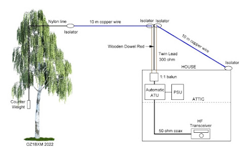
My antenna for the FT8 challenge is shown below. It is a centerfed wire dipole measuring 2 x 10 meters. The highest point is 7 meters above ground. The automatic ATU in the attic keeps SWR low on the coax-cable. 


 Wire antenna at OZ1BXM.

If you would like to monitor my progress, you can visit this page where my worked entities are listed: 

Vy 73 from OZ1BXM
My homepage: http://oz1bxm.dk/

tirsdag den 26. april 2022

Operating 144 MHz EME again

After some years of non-activity, I've decided to operate 144 MHz EME again. The equipment is in store, and I want continue in this exciting branch of ham radio. Full description of my EME station: http://oz1bxm.dk/eme/eme-station.html 

The different categories within 144 MHz EME stations are shown below.

Category     Ant-gain     Example antenna

Monster     24 dBd         16 x 9 element yagi

Big     21 dBd         8 x 9 element yagi

Mid-size     18 dBd         4 x 9 element yagi

Small     15 dBd         2 x 9 element yagi

QRP     12 dBd         1 x 9 element yagi

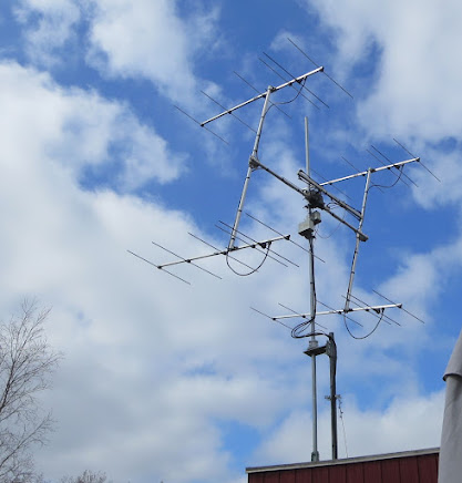
I've assembled a small EME station with 15 dBd antenna gain. The antenna array is 4 x 6 element yagi which provides 15 dBd gain. The picture below from 26-april-2022 shows my array.  

4 x 6 yagi for 144 MHz EME at OZ1BXM.

Azimuth rotor is Yaesu G-600 and elevation rotor is Kenpro KR-550. Both rotors are controlled by PSTRotator running on my Windows 10 PC.

I'll be a frequent visitor to the N0UK EME chat where EME-amateurs meet and arrange skeds.

I hope to work many initials in the time to come!

73 from OZ1BXM Lars Petersen, oz1bxm.dk

torsdag den 1. juli 2021

Mains power alarm

Our refrigerator must run at +5C at all times. But one day, the security relay of the house flipped and cut the power off. The power outage lasted 6 hours, and the temperature within the refrigerator rose to +15C. To avoid this in the future, I decided to build a mains power alarm, so I can take action if the power relay flips again.

Figure 1. Mains Power Alarm.

The PSU is connected to the mains and generates 12 V which energizes the relay coil. The relay is in position NO. If 12 V is lost, the relay changes to NC and activates the buzzer. SW1 can silence the buzzer.

The PSU in figure 1 is an AC adapter which is plugged into a 230 V AC wall outlet. The secondary of the AC adapter delivers 12 V DC. The green 12V lamp is on when 12 V DC (and mains) is present. Relay1 is active and breaks the buzzer circuit. The relay is a 12 V type. Any voltage transcients from the relay coil are bridged by D1 and will not damage the PSU.
 
The 12 V buzzer sounds when the coil of Relay1 is powered off during a mains power failure.   

Figure 2. PSU and metal box.

 The metal box in figure 2 measures 125 mm x 80 mm x 50 mm. The blue relay is taped to the wall.  


Figure 3. Front view.

Figure 3 remarks. Labels are in the Danish language. 

ALARM TIL means "Alarm is on".
LYSNET OK means "Mains Ok".

73 from OZ1BXM Lars
Homepage: oz1bxm.dk

torsdag den 17. juni 2021

Reading I2C addresses

Many electronic modules are controlled by the I2C-protocol. I2C builds upon the concept of masters and slaves connected via a 2-wire bus. There are two pull up resistors. Each of them should be higher than 1 kohm. Vdd is 3.3 V DC or 5 V DC. The wiring is shown in figure 1.
Figure 1. Wiring of I2C.

I2C bus speeds range from 100 kbit/s in Standard mode, 400 kbit/s in Fast mode, 1 Mbit/s Fast mode plus, and 3.4 Mbit/s in High Speed mode. Each master and each slave has its own, unique 7-bit address.

The I2C scanner is shown below in figure 2. The scanner software is running on my Arduino UNO R3. There are 4 wires connected to the slave unit.

+5V is connected to Vin on the slave
GND is connected to GND on the slave
A4 is connected to SDA on the slave
A5 is connected to SCL on the slave

The UNO is powered via an USB cable.

Figure 2. I2C scanner with Arduino UNO.

Figure 3. Output from the I2C-scanner

Output from the scanner is displayed in the Arduino IDE. Select Tools > Serial Monitor. An example output is shown in figure 3. 

The Arduino I2C address scanner was created by Arbi Abdul Jabbaar and it is described here:

73 from OZ1BXM Lars
Homepage: oz1bxm.dk

lørdag den 1. maj 2021

DC-receiver 0.1-100 MHz

Fig. 1. DC-receiver seen from the front.

Building your own equipment is not difficult if you buy ready-made modules and connect them together. I wanted to to build a DC (Direct Conversion) receiver with a broad frequency range. 

Fig. 2. Direct Conversion concept.

The concept of Direct Conversion is shown in figure 2. Four modules make up a SSB/CW receiver, and all modules can be obtained ready-made!

HF-filters are usually sold as kits or ready-made. I decided to make my own filter using a piece of Veroboard. The filter's circuit diagram and the Veroboard are shown below. 
Fig. 3. The 7 MHz bandpass filter.


Fig. 4. The filter is build with leaded components on a piece of Veroboard.

The mixer is a ready-made board centered around AD831. AD831 is an active, double-balanced mixer from Analog Devices and it runs on 10 V DC at 100 mA. The required LO level is just -10 dBm and max. input on the RF-port is +10 dBm.

Fig. 5. Active mixer 0.1 - 500 MHz.

The AF-amplifier is the well-known LM386 having 46 dB amplification. I tried to find a modern substitute, but that was difficult. Many audio ICs amplify something like 26 dB, and that is too low for DC-receivers which require 40 dB amplification or more.

Fig. 6. AF-amplifier with LM386.

The VFO is the ARDU-5351 kit sold by qrphamradiokits.com. The kit includes an OLED display, a rotary encoder, a frequency generator module (Si5351A), and the Arduino Nano. I soldered all parts onto the motherboard except the Nano, which is fitted using sockets. There was no soldering of SMD-components.

Fig. 7. The VFO kit.

As the VFO output is 7 dBm, I've added a 20 dB attenuator to lower the output and comply with the LO port level of the active mixer.

Components for power distribution and the S-meter rectifier are fitted on a piece of Veroboard as shown in figure 8 below.

Fig. 8. The 10 V power supply and the S-meter rectifier.


Fig. 9. Circuit diagram.

All modules are fitted into a metal enclosure which I acquired from Conrad Electronics (item 522953). The enclosure's front is seen in figure 1 above, and the rear is seen in figure 10 below. Figure 11 shows the open enclosure.

Fig. 10. Rear side of the DC-receiver.

Fig. 11. The DC-receiver with lid removed.

Vy 73 from OZ1BXM Lars

Homepage: http://oz1bxm.dk/